5985013298991
Price Quote Get an up to date pricing and availability quote for this product. Order online or over the phone.
Quality Commitment
Serving our customers with quality and safety first.
- AS9120 Certified
- Audited supply chain
- ITAR Registered
- DDTC Registered
- HAZMAT Certified
- Customer service objectives
- Every product 100% inspected

5985-01-329-8991 Specification Set by the OEM (see RNCC code 3)
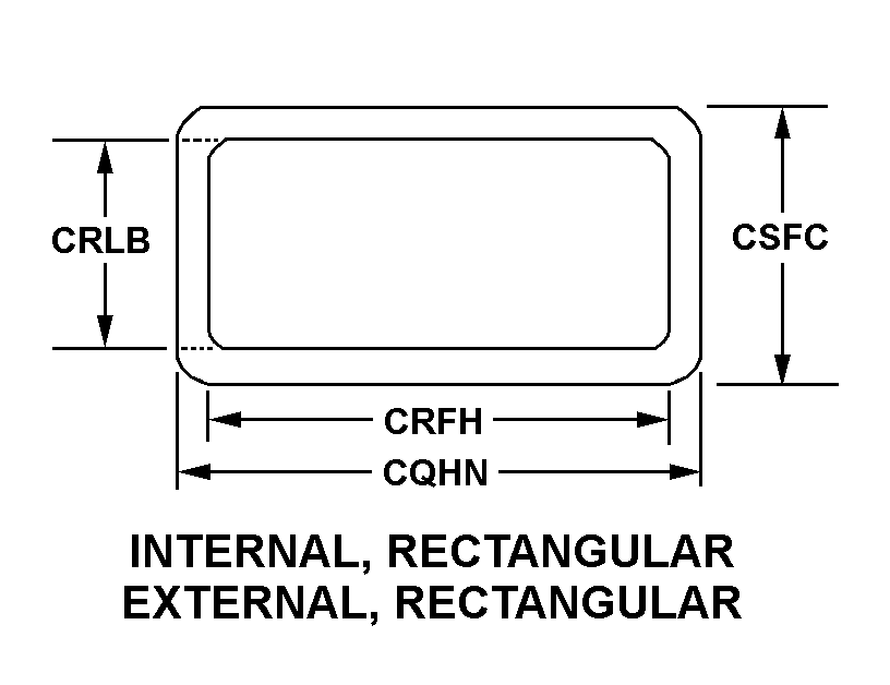
internal, rectangular external, rectangular
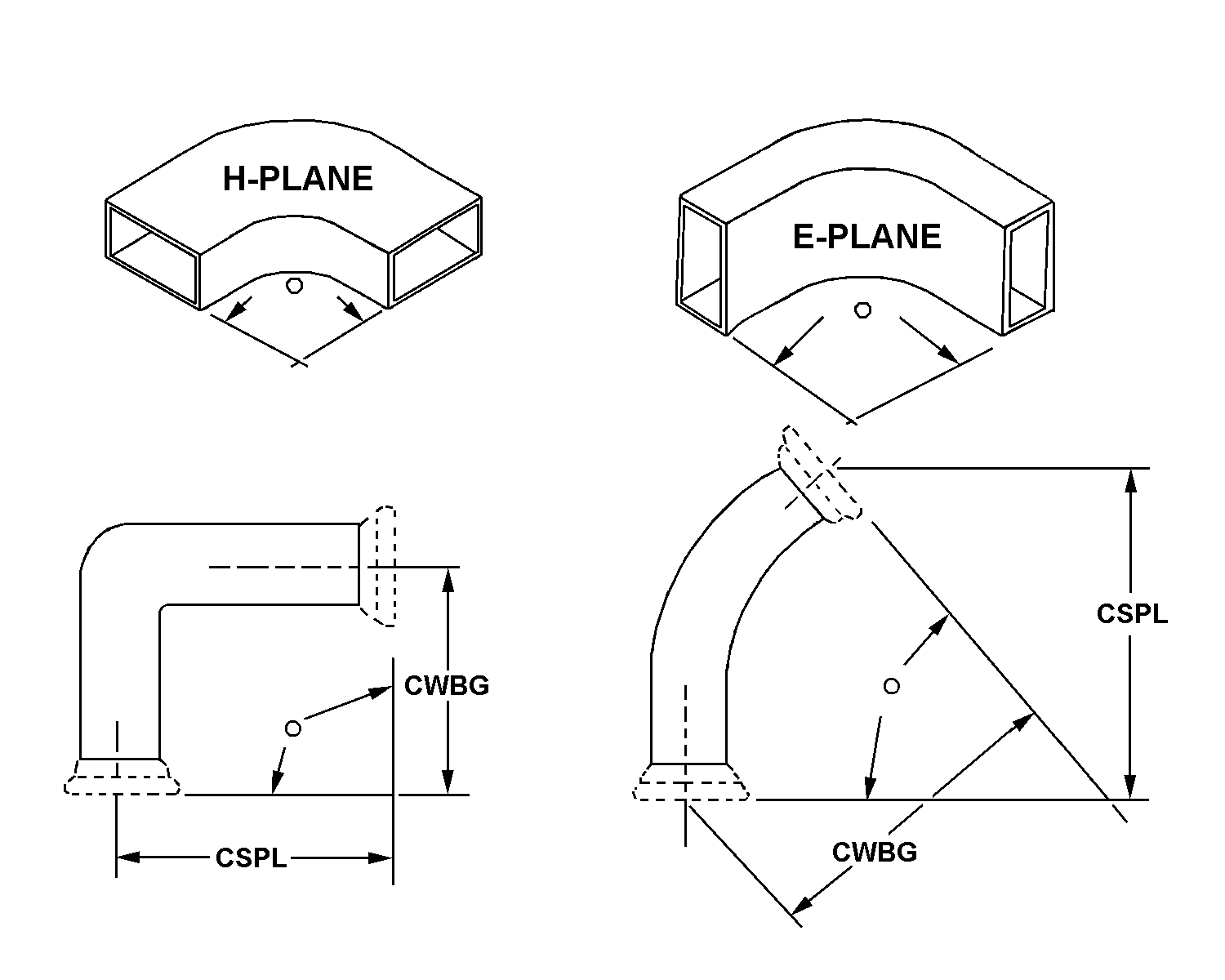
90.0 all bends H-Plane
seamless single tubing segment
unable to decodeunable to decodeunable to decode
2
1.118in. first flange and 1.126in. first FLANGE1.047in. second flange and 1.077in. second flange
0.396in. first flange and 0.404in. first FLANGE0.505in. second flange and 0.508in. second flange
1.610in. first flange and 1.640in. first FLANGE1.610in. second flange and 1.640in. second flange
1.610in. first flange and 1.640in. first FLANGE1.610in. second flange and 1.640in. second flange
1.406in. first flange and 1.437in. first flange
0.610in. first flange and 0.640in. first FLANGE0.423in. second flange and 0.453in. second flange
0.169in. first flange all connection facilities and 0.172in. first flange all connection facilities
unable to decodeunable to decode
1.000in.
0.900in.
0.400in.
0.500in.
1.750in.
4 threaded stud first flange all connection FACILITIES4 unthreaded hole second flange all connection facilities
choke type first flangecover type second flange
1.750in.
rigid single tubing segment
copper alloy first tubing segment and flangealuminum alloy second flange
any acceptable first tubing segment and flange all surfacesany acceptable second coupling all surfaces
bend type
antennas, waveguides, and related equipment
Cross Reference Parts Part numbers that meet the specification outlined on this page and set by the OEM
Identification Item Identification Guide (IIG) and Item Name Code (INC)


Definition Definition of approved item name (AIN): "WAVEGUIDE ASSEMBLY"
An item consisting of one or more definite lengths of straight or formed, flexible or rigid, prefabricated hollow tubing of conductive material. The tubing has a predetermined cross section and is designed to guide or conduct high frequency electromagnetic energy through its interior. One or more ends are terminated. May include common mounting of a switch, wave guide, a dummy load, electrical and other components such as waveguide section, cable terminal chamber and the like. Excludes coupler, rotary, radio frequency; coupler, directional; adapter, waveguide; and tuner, waveguide.
Packaging & Dimensions Packaging instructions, special markings, and approx. weight/dims
Packing shall be accomplished in accordance with table c.ii for the packing level specified. closure, sealing and reinforcement shall be in accordance with applicable specification for shipping container.
Packing shall be accomplished in accordance with table c.ii for the packing level specified. closure, sealing and reinforcement shall be in accordance with the appropriate shipping container specification.
Options can be exercised as to specific method of preservation or dod approved packaging materials to be used. however, basic preservation method shall be retained, supplemental data shall be complied with, and unit package dimensions shall not be increased by more than one inch. equal or better protection shall be given the item and there shall be no increase in the package cost.
No special marking.
Packaging Codes
OPI: Optional Procedure Indicator Code. A one position alpha code that indicates the allowable deviations from the prescribed requirements.
SPI No.: Special packaging instructions number.
LVL A/B/C: Indicates the type of shipping container required for level A, B, or C maximum packing protection.
SPC Mkg: A two position code that identifies the special markings applied to the container, which is part of the total pack to protect the contained item during preservation, packing, storage, transit and removal from the pack.
5985-01-329-8991 Material Hazmat, Precious Metals, Criticality, Enviroment, and ESD
Indicates there is no information in the hmirs. The nsn is in a fsc in table ii of fed std 313 and a msds may be required by the user. The requirement for a msds is dependent on a hazard determination of the supplier or the intended end use of item.
Item does not contain precious metal.
The item does not have a nuclear hardened feature or any other critical feature such as tolerance, fit restriction or application.
Identification Codes
HMIC: Hazardous Material Indicator Code. A one position code that identifies a hazardous item.
PMIC: Precious Metal Indicator Code. A one position code which identifies items that have precious metals as part of their content. precious metals are those metals generally considered to be uncommon, highly valuable, and relatively superior in certain properties such as resistance to corrosion and electrical conductivity.
ESD: Electrostatic Discharge. Indicates if an item is susceptible to electrostatic discharge or electromagnetic interference damage. electrostatic discharge damage occurs when an accumulation of static electricity generated by the relative motion or separation of materials is released to another item by direct contact. electromagnetic interference damage occurs when an item comes into proximity with an electrostatic or magnetic field.
ENAC: Enviromental Attribute Code. Identifies items with environmentally preferred characteristics.
CRITL: Criticality Indicator Code. Indicates an item is technically critical by tolerance, fit, application, nuclear hardness properties, or other characteristics.


